
Project · 2023 – 2026
Boaz: one machine, built twice
A DIY CoreXY filament printer, built once the way the hobby builds them and once the way a machine shop would. Same design, mostly the same parts. The difference showed up in every part it made.
- CoreXY
- Klipper
- Kinematic bed
- Belted Z
- Eddy probe
- Input shaping
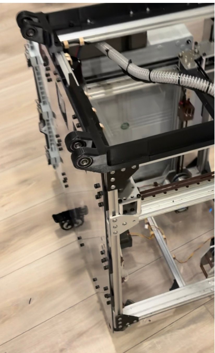
The question
Why build another printer?
Almost every convention in hobby printing is inherited from RepRap: printed structural parts, idlers on M5 screws, threaded-rod Z, rails aligned by eye. Those choices were optimized for a machine that could copy itself, not for one that could hold a tolerance.
The claim Boaz tests is narrow. The persistent quality gap is not a materials problem and not a kinematics problem. It is a measurement problem, and machine-tool builders solved it a century ago.
The method
The first build is the control
Boaz was built, run in production, diagnosed, and rebuilt. Both builds share the same design, the same kinematics and most of their components. What differs is how well the precision practices were carried out.
Eight criteria were fixed before construction, each with a number and a way to measure it. The comparison class is other machines a reader might build, not a factory product.
Process
From dependency graph to production plates
The finished machine is the last step of eight. Each step below is shown with the drawing, model, analysis or measurement that it produced. Select an image to enlarge it.
-
Plan
Map what blocks what
Before any aluminum was cut, the build was drawn as a dependency graph. The frame blocks the motion system, which blocks every judgement about print quality.
-
Sketch
One master sketch
A CoreXY belt path is a plane figure. Every belt run, idler center and rail line was placed in a single constrained 2D sketch before any solid part existed.
-
Model
CAD with real densities
Every toolhead part carries its true density in the model, so the center of mass can be checked. It sits in the plane of motion: drive force gives translation, not rotation.
-
Analyze
Finite elements pick the plate
Self-weight sag was computed against thickness. A 1/8 in plate sags 18.9 µm; the 5/16 in plate chosen sags 3.0 µm. Doubling thickness divides the error by four.
-
Prototype
Mock it up, and learn the limit
A printed PLA mock-up confirmed what CAD had already answered and misled on the two things that mattered: bearing seats and pin fits.
-
Fabricate
Ream, then press
Holes are hand-reamed to 4.95 mm for 5.000 mm ground pins: 0.05 mm of interference, pressed on an arbor press through jigs that hold each pin square.
-
Verify
Indicator against granite
All twenty pulleys and idlers were measured after pressing. Any assembly reading more than 0.001 in was taken apart and remade.
-
Run
Put it to work
A ten-day, 1,000-part contract at about 50 boxes a day, with roughly 100 plates in a row started without anyone adjusting the first layer.
Method
Five habits borrowed from machine building
Sandwich, don't cantilever
Idler stacks are trapped between two sheet-metal plates on machined standoffs. Belt tension then has no post to bend.
Reference against granite
The gantry is squared with a machinist square and a dial indicator on a granite plate. Never align a rail against the frame you are trying to correct.
Constrain exactly
The bed sits on a three-point kinematic coupling. Tramming becomes a firmware routine run by the bed's own three motors.
Locate on dowels
Ground dowel pins pressed into hand-reamed holes, about 0.05 mm of interference on a 5 mm pin, with the runout verified afterwards.
Sense, then decide
Eddy-current bed probing, accelerometer input shaping, driver telemetry. Measure the machine before tuning it.
Mechanics, then measurement, then software. Compensation polishes a machine that is already true. It cannot create one.
The machine
Boaz at a glance
Frame
Two-tier 20×40 aluminum extrusion, gusset plates at every corner, and more joints than a strength calculation asks for.
CoreXY motion
Stationary motors and crossed 9 mm reinforced belts on MGN12H rails, with a carbon-fiber X beam.
Triple belted Z
Three geared belt actuators at 1:5 lift the bed. No ballscrews, and the reduction divides the step angle.
Kinematic bed
Cast ATP-5 tooling plate on a three-point Maxwell coupling, trammed by its three motors.
Klipper + TMC5160
Raspberry Pi host, SPI drivers tuned live, and 48 V on the XY pair for torque at speed.
Eddy-current probe
100 × 100 point meshes in minutes, and first layers nobody has to watch.
CPAP part cooling
A remote high-flow blower feeds the toolhead, so cooling costs no carriage mass.
Input shaping
Resonances measured with an accelerometer and shaped in firmware. X is clean; Y still shows two modes.
The model
Designed in CAD, down to the fasteners
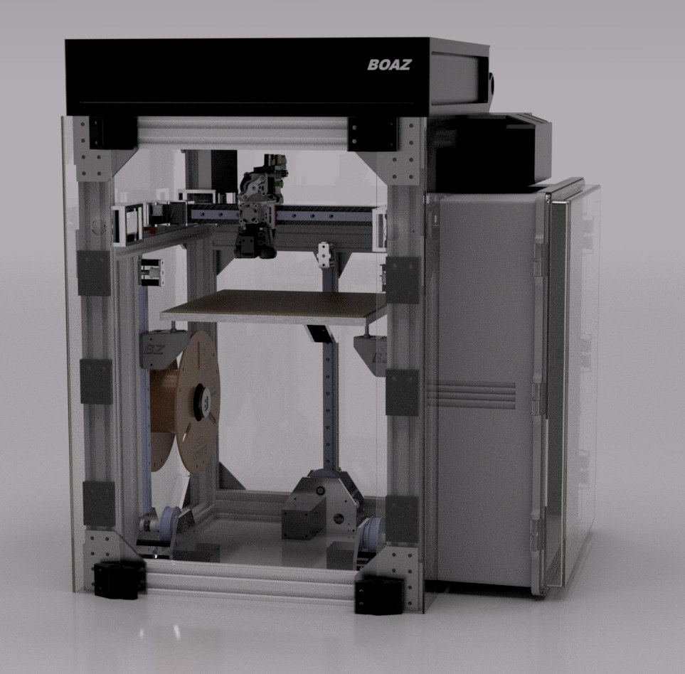
This is the final assembly, exported from the model after the rebuild. The sheet-metal profiles are extruded from one master sketch, so a change to a belt run or an idler position moves every part that depends on it.
- Motors mounted diagonally, which recovered about 50 mm of rail travel on each axis.
- Idler stacks trapped between two plates on machined standoffs.
- Three belted Z actuators at a 1:5 reduction under a three-point kinematic bed.
Drag to rotate. Scroll or pinch to zoom.
First build
What broke first
The first build's failures were specific enough to be instructive. The rebuild is where most of the engineering lives.
Press fits, misunderstood
Holes reamed to nominal size gave clearance, not interference. The pins measured 0.04 mm undersize and one idler ran visibly skewed. The rebuild reamed 4.95 mm holes for 5.000 mm pins and verified every joint.
A PCB heatbed
A Prusa MK52 on a partial mount left 1.6 mm of deviation across the bed. No mesh density rescues a warped plate. It took a cast tooling plate to fix.
3D-printed structure
Printed Z-actuator bodies bent under standing belt tension and crept near the heated bed. Load-bearing and locating parts went to sheet metal and machined spacers.
Belt tension as a dial to max
Tensioning one belt and then the other racks the gantry, and the skew lands in every part. Matched tension on proper 9 mm belts removed the slip.
The pattern behind all four: a heuristic fix resolves the symptom and destroys the information you needed to diagnose it.
Results
Before and after, in numbers
Same design, same kinematics, mostly the same parts. These are the measurements that moved between the first build and the rebuild, and the one that did not move far enough.
Eight times flatter, measured at 10,000 points where the first mesh had 70.
The first build's pins ran 0.04 mm undersize in nominal holes, so idlers leaned. Reamed holes made the fit an interference.
Total indicator reading on every one of the twenty assemblies kept. That is about 25 µm.
The first build needed Z offset jogged on every plate. The target was ten in a row.
Twenty percent under the target, on the first attempt, with the model unmodified.
Not met. The Y sweep shows two resonance peaks. X met it at 20,900 mm/s².
Scorecard
Eight criteria, fixed before the build
Seven were met by the rebuilt machine. The first build failed at least the first four.
| Criterion | How it was measured | Target | Rebuilt machine | Outcome |
|---|---|---|---|---|
| Geometric accuracy | Califlower artifact; X, Y and both diagonals | Skew < 0.1°; axis error < 0.2% | Met after firmware correction. The pre-correction values were not recorded. | Met |
| Functional tolerance | A printed threaded lid engages and turns freely | ≤ 0.2 mm | Lids engage freely. The first build could not print the part. | Met |
| Bed flatness as firmware sees it | Klipper bed mesh over the full print area | Envelope ≤ 0.2 mm | 0 to 0.2 mm over 100 × 100 points at 70 °C | Met |
| First-layer autonomy | Consecutive production plates started without jogging Z offset | ≥ 10 plates | About 100 plates | Met |
| Locating-feature runout | Dial indicator on each pressed idler, several angles and heights | < 0.001 in TIR | Met on every assembly retained; those above the limit were remade | Met |
| Dynamic behavior | Klipper resonance sweep, accelerometer on the toolhead | One dominant peak; ≥ 20,000 mm/s² | X: one peak, 20,900 mm/s². Y: two peaks, 9,500 mm/s². | Not met |
| Speed and quality | #SpeedBoatRace 3DBenchy, model unmodified | ≤ 20 min at acceptable quality | 16 minutes, first attempt | Met |
| Sustained production | Parts per day over a multi-day contract | ≥ 50 per day | About 50. The comparison machine did 60. | Met, at its floor |
Reported honestly
Where the comparisons are weak, or lost
The claim is about construction method against other machines a reader might build. It is not about beating a mass-produced machine on throughput per dollar.
The 1,000-part contract
Boaz made about 50 PETG boxes a day for ten days. A $300 Elegoo Centauri Carbon beside it made about 60. Boaz lost by roughly 20%. What the contract did establish is functional tolerance: threaded lids that engage freely.
The charity toy run
About 200 toys against about 150 from a Prusa i3 alongside it. The comparison flatters Boaz: the new machine got tuning and attention that the Prusa did not.
The paired Speed Benchy
At an equal 16 minutes, Boaz's Benchy has a cleaner smokestack and fewer artifacts at bow and stern than a HevORT's. One paired print is an anecdote, not a margin.
Input shaping
No matched before-and-after resonance sweep exists, so input shaping cannot be credited with a measured improvement.
Reflection
What the project taught
From the book's closing chapters.
The first effort went to the wrong problem
The project began by copying open designs built from printed plastic. In an early mock-up those parts broke under ordinary assembly loads, not after long service. That ended the plastic-structure phase.
The new idea was measurement, not parts
A community of builders who use granite, indicators and machinist squares showed that shop practice applies at this scale. The machine does not need to be a machine tool. It needs to be built like one.
A budget of about $100 a month
Everything was bought in small increments. That left time to think between purchases, and it compressed testing at the end. Several choices that look like engineering judgements were budget decisions.
Rebuilding instead of settling
The first machine worked and printed 200 toys. Rebuilding it anyway is what produced the evidence: because the two builds differ in execution and not in design, the first is the control.
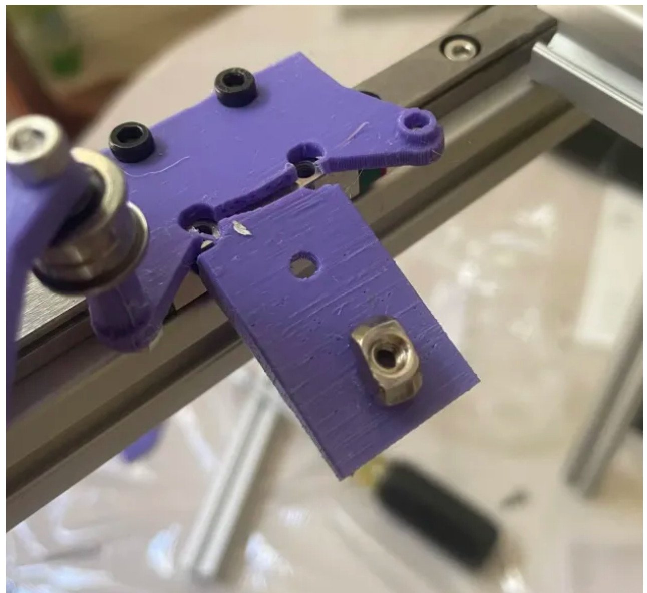
Fix causes, or accept that you will never know which of your fixes worked. Building Boaz, chapter 28

Shown in public · October 2026
Exhibited at Maker Faire Rocklin 2026
“Boaz: A DIY 3D Printer, Built Twice” was accepted as an exhibit at Maker Faire Rocklin, at Sierra College on October 3, 2026: the machine running, with a poster on the method and the results.
Conclusion
Eleven rules, each with evidence
Each rule was earned by a failure on the first build and a measurement on the second. A rule without evidence attached is an opinion.
- Stiff frame in large-section extrusion, gusset-joined, with more joints than strength requires.
- Enclose the machine.
- Enclose the electronics separately.
- Design the toolhead for flow, cooling and center of mass.
- Put load-bearing and locating parts in sheet metal and metal spacers.
- Idlers on dowel pins in reamed holes, about 0.05 mm of interference on a 5 mm pin.
- Square the frame on granite, during assembly.
- Align rails and verify pressed joints against external granite, never against the frame.
- Remove mass from what moves; add it to what does not.
- Adopt sensing that removes the human.
- Calibrate with printed artifacts, and again after every mechanical change.
Gallery
More from both builds
Photographs, CAD and measurements. All images are the author's own.
Go deeper
The full account is in the book
Twenty-nine chapters of theory, failures and fixes, with the evidence behind each of the eleven rules. The paper, article, poster and slides are in the library.